Sunday 12 August 2012

R.M.S Value and Average Value


R.M.S Value Or Effective Value
Definition:
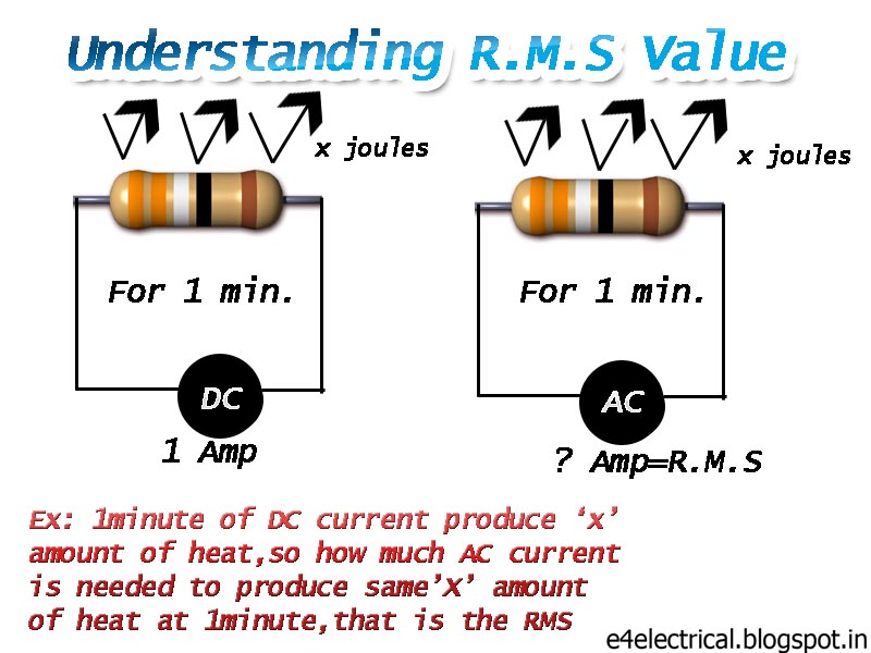
The steady current which when flowing through a given resistor fora given time produces the same amount of heat as is produced by the alternating current when flowing through the same resistor for the same time is called R.M.S or effective value of the AC .
In electrical mainly for AC we are always take R.M.S value or Effective values for calculation.
Suppose we say the supply voltage in house 230volts, it means that the R.M.S value of the supply voltage is 230volts. Sometimes we can denote RMS value of voltage by E. As a whole ,we use V (or E) and I for RMS values of A.C voltages and currents respectively.
General formula is
                        R.M.S value= Area of squared wave/base

To find RMS value for AC is   =  Im/√2           (it is only for symmetrical sine waves)
Average Value:
            The average value of  AC is defined as the D.C current which transfers across any circuit the same charge as is transferred by that AC during the same time..
Average value of AC=2/π*Im
For rectangular wave form RMS value = average value
                        Average value= Area under the curve/base

Sunday 3 June 2012

Faults and Relays.


TYPES OF FAULTS AND RELAYS
In power system only two types of faults are present
1.     Over-current Fault
2.     Earth Fault
In these two main categories  there are many types of faults present
Example:
1.     Over-current Fault
·        Line to Line Fault
·        3 phase fault  etc.
2.     Earth Fault
·           Line to ground Fault
·           Double Line To Ground Fault etc.
So relate with equipment and environment, we use so many types of relays used to protect the power system elements.

TYPES OF RELAYS:
1.O/C & E/F RELAYS
These relays are used for general protection.It give protection over earth fault and over current fault.The main thing we have keep in mind that it is used in short transmission lines up to 33KV limit(may be used in 66KV).
2.Distance Relays
This Relay is used as over current relay in long transmission high voltage lines. It is accurate than ‘O/C & E/F RELAYS’ and we can figure out the exact position of fault.So it is much helpful to locate the fault in long tx.line.
3.Restricted earth fault relay.
This relays are used in equipment protection mainly for transformer.It is connected to the C.T in the earthed neutral link,we called a Neutral C.T.It is actually a earth fault relay that find any internal insulation failure or heavy earth fault related with equipment surrounding.
4. Differential relays
The definition of such a relay is “one that operates when the vector difference of two or more similar electrical quantities exceeds a predetermined amount.That means in a trans former we know it primary and secondary voltages so the ratio of Pr. And Sec. Always constant so if any abnormality occur the ratio will change and relay will operate.This is also for equipment protection.
5.Master Relay  
All the above relays are connected to master relay in a panel board and it will operate the breaker.


Friday 25 May 2012

Protective scheme

Protective Scheme For Power System

          Hi friends  now we can see the protective action in a power system.Here i am going to explain you the very basic protective scheme.Don't think this is all,the power system contain very complex protective schemes because each and every devices are very costly and dangerous. Here i just illustrate only one P.T and C.T actually each phase has its own C.T and P.T . 

            The C.T is always series to the mains and its secondary should be short circuited(ie.always in a closed circuit).The P.T is always parallel with mains open circuited secondary.In most of the area of power system the C.T is the protecting device, ie we take the current reference . P.T is mainly for the metering of voltage.I think at the generating side only the frequency and voltage terms come into protective action.


            Both the C.T and P.T has many number of secondary  cores for various purposes. Mainly the C.T has dedicated cores for Metering,Protection,Backup Etc..The cores has some standards also like 5P10,.5s etc..according to the accuracy and other parameters.The C.T secondary measures in Ampere. it may be 1A to 5A normally. The P.T secondary measures in voltage, and it is normally 110v AC. we can discuss about C.T and P.T in the next post.........................THANK YOU


Tuesday 22 May 2012

Name Plate Examples

SAMPLE NAME PLATE DETAILS 


33 KV Vacuum Circuit Breaker.

 33KV current Transformer
 L.A 11KV

 P.T 33 KV side

 11kv vacuum Circuit Breaker

 33/11 kv 5MVA transformer


Monday 21 May 2012

Real And Reactive Power


KVA,KW,KVAR,KWh,Kvar.....
As an electrical engineer we seen a lot as KW,MW,KVA etc. These are some units related with power and energy. It varies with the nature of the power and energy. Before that we can just see what is reactive and real power.
REACTIVE POWER:
The book definition is ‘it is the power absorbed by the inductor or released by the capacitor’. We know in AC circuit only the inductance and capacitance are present. It may be a line capacitance or winding inductance.It is the imaginary power etc.
          This reactive power is simply circulating power due to the phase shift between the source and the loads. This additional power that appears to be flowing requires the equipment to be rated higher than that for a system operating at unity. Obviously these circulating currents while real..produce no useful work. It is the job of the Electrical Engineer to correct the load reactance as close as possible to unity to increase efficiency and reduce operational costs. That means simply match the capacitance and inductance.

          Start now,
Total power     KVA   =   Kilo Volt Amp(v*I)
Real power      KW    =    Kilo Watt(v*I*cosΦ)
Reactive power KVAR = Kilo Volt Amp Reactance  (v*I*sinΦ)

Total power  KVA=KW+jKVAR
Power * Time= Energy 
Eg:KW*Hour=KWh(unit of electrical energy)
Friends, the field of reactive power is a wide area and researches are now going on, so i am not yet expert. The interesing fact is Reactive power is needed to transport the real power!! So we minimize it what ever we can. We use capacitor banks and other FACTS(Flexible AC Transmission System) devices for minimize it.


Sunday 20 May 2012

Star and Delta Connections


STAR AND DELTA CONNECTIONS
We seen the 3 phase concept and now we can discuss the star and delta connection for 3 phase supply. Actually where is these connections exist? The answer is at
·       Transformers(Both power and instrumentation).
·       At motor winding.
·       At generator winding.
Actually where we handle the 3 phase supply directly, we can prefer the star or delta connection. Previous post i mentioned that only 3 phase loads are motors,so you may confuse about the transformers, actually transformer is not a load. It just change the voltage level.
Delta connection is also used to connect the windings of most three-phase motors because the phase windings are perfectly balanced and, therefore, do not require a neutral connection.
           Making a star connection has the advantage that two voltages
become available – a line voltage between any two phases, and a
phase voltage between line and neutral which is connected to the star point.
          In any star-connected system currents fl   ow along the lines ( IL), through the load and return by the neutral conductor connected to the star point. In a balanced  three-phase system all currents have the same value and when they are added up by phasor addition, we find the resultant current is zero.

3 Phase Concept


WHY WE USE 3 PHASE ?


In the electrical field we use only 3 phases exactly. Not more or less,Why? Because we minimum of 3 phases to produce a rotating magnetic field(RMF). We studied that more than one phase is enough to produce a torque, but imagine 2 equal magnitude phases come into action the phase angle will be 1800  and will oppose each other.
So we use 3 phases to produce a rotating magnetic field and can carry more power than a single phase. Remember one thing, the only 3 phase AC loads are motors. No other loads are directly consume or use the 3 phase AC supply. You can easily understand the concept with an IC engine with 3 cylinder.

Friday 18 May 2012

Structure Of Power System


STRUCTURE OF POWER SYSTEM
So we discussed about the need for High Voltage,Now we can see the structure of power system according to the voltage level and the position of transformers.

          From the structure we clear that at generation and distribution, the voltage is comparatively less. At the transmission we have very High Voltage. You can imagine the need for it. At transmission we have long line and loss will high so we use high voltage at this side simple.......!!
The voltage levels i mentioned above are just a common levels, It may be vary according to the design.I personally found that the small head hydro plants have a generating  voltage of 3.3Kv.at this case the sending end transformer has the voltage ratio of 3.3Kv/11Kv . 

Thank You For Reading Keep Follow me.........

Thursday 10 May 2012

Need for High Voltage


Why we are using  High Voltage AC supply..?

Most our consumer gadgets are using DC supply like TV,Computer,Laptop etc.,then why we are using AC ?
          Because the AC supply voltage only we can efficiently and easily stepup or stepdown. We can also stepup or stepdown the DC with the help of modern power electronics devices,but it is complicate and not much efficient.You all know the transformer is the most efficient machine in electrical(more than 90%).
          Again the question is why stepup or stepdown the voltage? We can find the answer from the following formula.
We know power P=V*I
Replace ‘V’ with ‘IR’(ohm’s law)
Power P=I2R
This power equation shows where ever a resistance present it will consume some power as I2R and it proportional to the  square of the current.
          We know our current carrying conductor has some resistance and they will sure consume the electric power. We don’t need the conductor to consume the power actually it just waste the power.Our requirement is to use the power only by the equipment. To avoid this problem we need to reduce the current!
          Only way to minimize the current without changing the power requirement is to stepup the voltage of the supply through a transformer.
          The following practical example will clear the whole concept.
Imagine you have a small factory 50KM away from an electric substation and you need 1000KVA of total power.
Case 1:
   You are going to take that without stepup the voltage, so V=230V
Power P=VI   We know P=1000KVA,V=230V
Current I=1000KVA/230V=4347.82A
Case 2:
You are going stepup the voltage and  transmit,so V=11KV
Power P=VI   We know P=1000KVA,V=11KV
Current I=1000KVA/11KV=90.909A
From the case 1 and 2 we can see that higher the voltage lower the current. Advantages are
1.    Less current so less the losses.
2.    Need Small Conductor because less current.
Only Disadvantage is we need two  transformer and suitable insulation.But it is negligible when we account this for a long time of operation.

Wednesday 9 May 2012

Simple Basic

Let’s Start from the Basics

We heard a lot about the Current,Voltage,Resistence,Inductance etc...So i am not going  to explain it again....just visualize it with a simple picture.My personal advice to learn electricity by visualize everything..Because electricity we can’t see,touch!!.....Here i am illustrate by a water tank...
            From the picture we can understand that to carry more current we need big conductors ...Also we need sufficient Voltage(head of water in the picture).
Convert 
                                 Water= Electrons
                                 Water Tank = source of electricity
                                  Pipe= Electric conductor
        
Through the way,the water may experience some difficulties cause by friction,Like wise in electrical the current also experience some opposition caused by RESISTANCE ‘ .

My First Post

Hai All this blog aim for all electrical field friends.Here i am going to share my electrical field experiences that i was got from various working sites.For a fresh electrical engineer or what ever may be...it is hard to know the practical thing apart from your theories.So use this blog to study  your ABC in electrical....Keep touch with me.